
HVAC & Plumbing
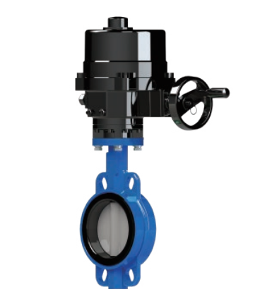
Butterfly Valve with Electric Actuator – Fig. 2302-GE
Brand

HVAC & Plumbing
Butterfly Valve with Electric Actuator – Fig. 2302-GE
Read full product detailsSpecifications
| Material | Ductile Iron, Stainless Steel, PTFE, NBR, EPDM, Malleable Iron, Aluminum Alloy |
|---|---|
| Body | Ductile Iron EN-GJS-450-15 |
| Type | Ductile Iron EN-GJS-450-15 |
| Includes | Body, Disc, Shaft, Seat, Bushings, O-Rings, Electric Actuator |
| Pressure rating | PN16 |
| Size range | DN40–DN600 (WRAS: DN50–DN600) |
| Standards | BS EN 593, MSS SP-67, BS EN 12266, EN 558, ISO 5752, EN 1092-2, ISO 5211, IEC 60068-2-6 |
| Application | Water, water distribution and ethylene glycol solutions up to 50% |
Applications
Product details
Product Overview
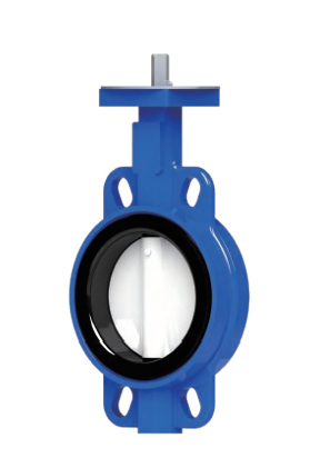
The Fig. 2302-GE Butterfly Valve with Electric Actuator is designed for efficient and precise flow control in water distribution and industrial pipeline applications. It combines a robust ductile iron valve body with an electrically operated actuator, providing automated valve operation and dependable performance.
Available with multiple GE-series electric actuators, this valve supports different torque requirements, control signals and operating configurations.
Key Features
- Completely sealed in both directions with an airtight sealing design.
- Precision-machined valve plate provides low torque and long service life.
- Three self-lubricating bushings help prevent valve stem deflection.
- Optimized flow characteristics with low-pressure loss.
- Passed surface salt spray and corrosion resistance testing.
- Four flange positioning holes ensure correct positioning during installation.
- Can be installed in any direction.
- Maintenance-free design.
- Silicone-free versions available for special industrial applications.
- Available with electric actuator configurations from GE03 to GE350.
Technical Specifications
| Specification | Details |
|---|---|
| Product Figure | 2302-GE |
| Valve Type | Butterfly Valve |
| Actuation | Electric Actuator |
| Pressure Rating | PN16 |
| Design Standards | BS EN 593 / MSS SP-67 |
| Testing Standard | BS EN 12266 |
| Face-to-Face Standard | EN 558 / ISO 5752 |
| Side Flange Standard | EN 1092-2 |
| Top Flange Standard | ISO 5211 |
| Size Range | DN40–DN600 |
| WRAS Size Range | DN50–DN600 |
| Suitable Medium | Water and up to 50% Ethylene Glycol Solution |
| Protection Rating | IP67, optional IP68 |
| Environmental Temperature | -25°C to 70°C |
| Noise Level | Less than 75 dB within 1 metre |
| Inlet Size | 2 PG13.5 (≤100 mm); 2 PG16 (≤100 mm) |
| Machine Rating | Class F, overheat protection, ≤135°C; optional Class H |
| Anti-Vibration Standard | IEC 60068-2-6 |
Material Specifications
| No. | Component | Material | Specification |
|---|---|---|---|
| 1 | Body | Ductile Iron | EN-GJS-450-15 |
| 2 | Bushing | PTFE | — |
| 3 | Shaft | Stainless Steel | SS410 |
| 4 | Seat | NBR / EPDM | — |
| 5 | Disc | Ductile Iron / Stainless Steel | EN-GJS-450-15 / CF8 / CF8M |
| 6 | Taper Pin | Stainless Steel | SS416 / SS316 |
| 7 | O-Ring | NBR / EPDM | — |
| 8 | Bushing | PTFE | — |
| 9 | Lever | Malleable Iron | — |
| 10 | Gear Box | Ductile Iron | EN-GJS-450-15 |
| 11 | Electric Actuator | Aluminum Alloy | — |
Operating Temperature
| Seat Material | Temperature Range |
|---|---|
| EPDM | -10°C to 120°C |
| NBR | -10°C to 80°C |
| WRAS Configuration | 1°C to 85°C |
Performance Testing
| Test | Pressure |
|---|---|
| Shell Test | 24 bar |
| Seal Test | 17.6 bar |
Electric Actuator Specifications
The GE-series electric actuators are available in multiple configurations to meet different torque, operating time and automation requirements.
Common Actuator Features
- Torque range: 10–20,000 Nm.
- IP67 protection, with optional IP68 protection.
- IP68 configuration is defined as 7 metres underwater without leakage for 72 hours.
- Working temperature: -25°C to 70°C.
- Noise level: Less than 75 dB within 1 metre.
- Operating duty: S2 – 15 minutes, maximum 600 starts per hour.
- Adjustable duty: S4 – 50%, maximum 600 triggers per hour, optional 1,200 triggers per hour.
- Overheat protection and comprehensive fault alarm functions.
Control and Input Signals
| Parameter | Specification |
|---|---|
| Input Control | AC/DC 24V or AC 110/220V |
| Input Signal | 4–20 mA, 0–10V, 2–10V |
| Input Impedance | 250 Ω (4–20 mA) |
| Output Signal | 4–20 mA, 0–10V, 2–10V |
| Output Impedance | 750 Ω (4–20 mA) |
| Reverse Signal | Supported |
| Discharge Mode | Supported |
| Dead Zone | ≤2.5% |
Fault Monitoring
The electric actuator supports comprehensive fault alarms, including:
- Power outage
- Motor overheating
- Phase loss
- Over-torque
- Signal interruption
- Phase sequence alarm (three-phase applications only)
Note: GE03, GE05 and GE08 models do not include the torque option.
Adaptable Voltage
Available power supply configurations include single-phase and three-phase options.
- Single-phase: 50Hz / 60Hz, with multiple voltage configurations including 110V, 120V, 220V, 230V and 240V.
- Three-phase: 50Hz / 60Hz, with multiple voltage configurations including 220V, 240V, 380V, 400V, 440V, 460V and 480V.
- DC: 24V ±10%, where supported.
GE03, GE05 and GE08 are suitable for single-phase applications only. GE170 and above cannot be equipped with 24V.
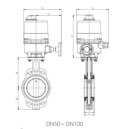
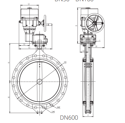
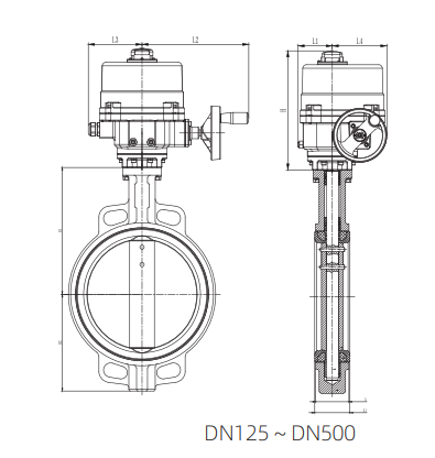
Product Dimensions
All dimensions are in millimetres (mm).
| DN | Inch | H1 | H2 | A | A1 | L1 | L2 | L3 | L4 | L5 | H | Actuator |
|---|---|---|---|---|---|---|---|---|---|---|---|---|
| 50 | 2″ | 141 | 69 | 42 | 46 | 150 | 135 | 170 | — | — | 192 | GE03 |
| 65 | 2½” | 150 | 76 | 45 | 49 | 150 | 135 | 170 | — | — | 192 | GE03 |
| 80 | 3″ | 156 | 95 | 45 | 49 | 150 | 135 | 170 | — | — | 192 | GE03 |
| 100 | 4″ | 168 | 110 | 51 | 55 | 150 | 135 | 170 | — | — | 192 | GE08 |
| 125 | 5″ | 187 | 129 | 55 | 59 | 79 | 243 | 123 | 123 | — | 268 | GE10 |
| 150 | 6″ | 206 | 142 | 55 | 59 | 79 | 243 | 123 | 123 | — | 268 | GE20 |
| 200 | 8″ | 231 | 176 | 60 | 64 | 79 | 243 | 123 | 123 | — | 268 | GE30 |
| 250 | 10″ | 270 | 212 | 67 | 72 | 109 | 280 | 146 | 187 | — | 327 | GE60 |
| 300 | 12″ | 328 | 249 | 76 | 80 | 109 | 280 | 146 | 187 | — | 327 | GE80 |
| 350 | 14″ | 368 | 272 | 76 | 80 | 109 | 280 | 146 | 187 | — | 327 | GE100 |
| 400 | 16″ | 400 | 333 | 102 | 107 | 109 | 280 | 146 | 187 | — | 327 | GE130 |
| 450 | 18″ | 422 | 364 | 114 | 119 | 128 | 333 | 163 | 242 | — | 378 | GE170 |
| 500 | 20″ | 480 | 389 | 127 | 132 | 128 | 333 | 163 | 242 | — | 378 | GE230S |
| 600 | 24″ | 562 | 459 | 151 | 267 | 156 | 308 | 186 | 118 | 242 | 532 | GE350 |
Actuator Operating Options
The product is available with different operating configurations:
- Electric Actuator
- Electric Actuator with Handwheel
- Planetary Gear Mechanism with Handwheel
Actuator selection depends on valve size, torque requirements and control configuration.
Surface Treatment
Default surface treatment:
Epoxy Powder / Polyurethane – RAL 5015
Applications
- Water distribution networks
- Industrial water pipelines
- Water treatment systems
- Automated pipeline control
- Ethylene glycol solution applications (up to 50%)
For actuator selection, voltage configuration and special operating requirements, please contact the manufacturer.
Related products
HVAC & Plumbing
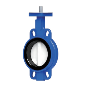
Fig.2302
Technical Specifications Outside Diameter (OD): 406 mm – 1,524 mm Custom Diameters: Available to meet project-specific requirements. Steel…
HVAC & Plumbing
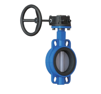
Fig.2302-G
Key Features Bi-directional airtight sealing. Low-torque operation with long service life. Self-lubricating bushings for smooth operation. Excellent flow…
HVAC & Plumbing
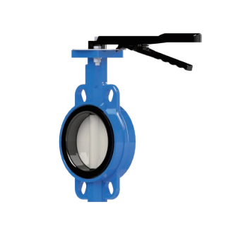
Fig.2302-L
Key Features Bi-directional airtight sealing. Low-torque operation with long service life. Self-lubricating bushings for smooth operation. Excellent flow…
Request a Quotation
Send sizes and specifications — we reply with price and availability.